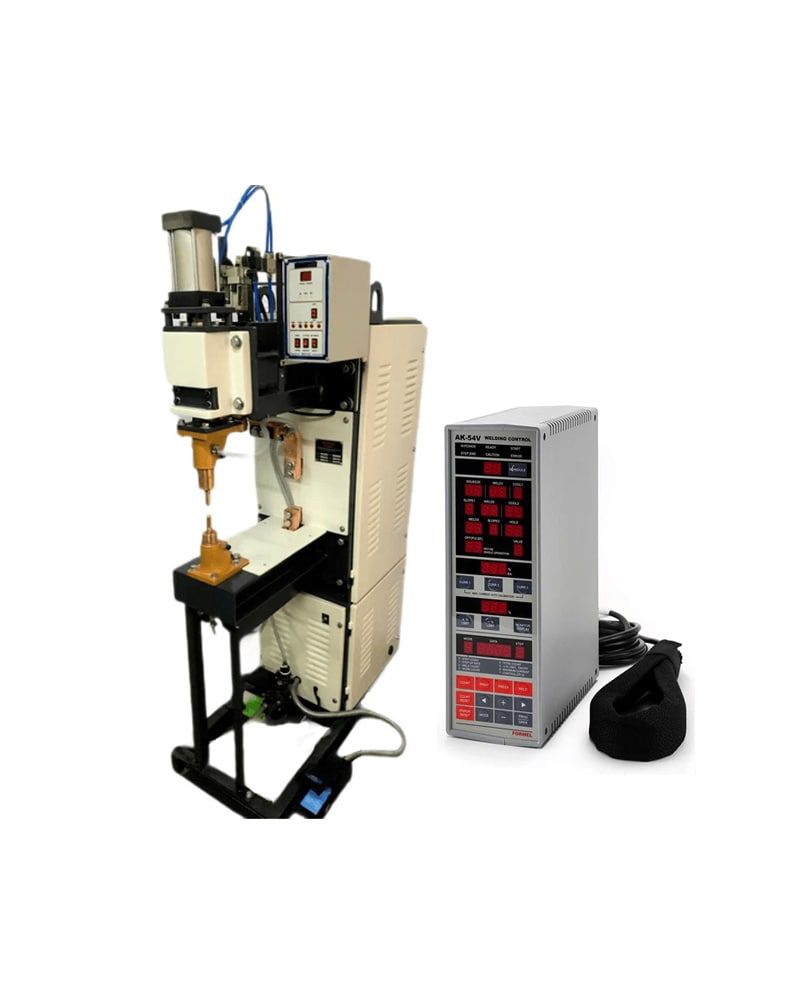
Projection Welding Machine
Key Features :
- Suitable for weld nuts, bolts, studs, mesh and cross wire welding
- High-strength and consistent projection weld quality
- Heavy-duty machine structure for long service life
- Water-cooled arms and electrodes
- Pneumatic pressure system for uniform electrode force
- Low maintenance and reliable performance
- Ideal for automotive and sheet-metal fabrication applications
Description
Projection Welding Machine
Projection Welding Machines are specially designed for high-strength, repeatable welding of weld nuts, weld bolts, cross wires and mesh on mild steel and stainless steel sheets. These machines ensure precise current control, uniform weld quality and high productivity, making them ideal for automotive, fabrication and industrial manufacturing applications.
Model: SP-25PR (25 KVA)
- Projection weld S.S. / M.S. weld nuts and weld bolts
- Sheet thickness range: 1 – 4 mm
- Weld nut / bolt size: M5 – M10
Mild Steel Sheet (M.S. / CRS)
- Thickness: 0.6 – 3.5 mm (2 × mm)
- Thickness: 0.0236″ – 0.1378″ (2 × inches)
- US Sheet Gauge: 10 – 24
- SWG Gauge: 9 – 23
Stainless Steel Sheet (S.S.)
- Thickness: 0.6 – 3.5 mm (2 × mm)
- Thickness: 0.0236″ – 0.1378″ (2 × inches)
- US Sheet Gauge: 10 – 24
- SWG Gauge: 9 – 23
Cross Wire / Mesh Welding
- Mild Steel Cross Wire or Mesh: Ø 1.2 – 7.0 mm
- Stainless Steel Cross Wire or Mesh: Ø 1.2 – 7.0 mm
|
Table – Sheet Metal Spot / Projection Welding Application
| |||||||||||||
|
Model
|
SP-10PR
|
SP-15PR
|
SP-20PR
|
SP-25PR
|
SP-30PR
|
SP-40PR
|
SP-50PR
|
SP-75PR
|
SP-100PR
|
SP-150PR
|
SP-200PR
|
||
|
Rating @ 50% Duty Cycle (KVA)
|
10
|
15
|
20
|
25
|
30
|
40
|
50
|
75
|
100
|
150
|
200
|
||
|
Throat Depth (mm)
|
460
|
||||||||||||
|
Throat Depth (inches)
|
18
|
||||||||||||
|
Nominal Throat Clearance (mm)
|
220
|
350
|
|||||||||||
|
Nominal Throat Clearance (inches)
|
8.6
|
14
|
|||||||||||
|
Model
|
SP-10PR
|
SP-15PR
|
SP-20PR
|
SP-25PR
|
SP-30PR
|
SP-40PR
|
SP-50PR
|
SP-75PR
|
SP-100PR
|
SP-150PR
|
SP-200PR
|
||
|
Welding Range: S.S.lM.S. Weld Nuts and Weld Bolts (M) Welded on Sheet With Thickness Range: 1mm-4mm
|
M3–M4
|
M4–M6
|
M4–M8
|
M5–M10
|
M6–M12
|
M6–M14
|
M8–M16
|
M8–M18
|
M10–M20
|
M10–M22
|
M12–M25
|
||
|
Model
|
SP-10PR
|
SP-15PR
|
SP-20PR
|
SP-25PR
|
SP-30PR
|
SP-40PR
|
SP-50PR
|
SP-75PR
|
SP-100PR
|
SP-150PR
|
SP-200PR
|
||
|
Welding Range (Thickness) Stainless 2xmm
|
Mild Steel Sheet IM.SI
|
Max.2xmm
|
2.0
|
3.0
|
3.025
|
3.5
|
3.75
|
4.0
|
4.5
|
5.0
|
6.0
|
7.0
|
7.5
|
|
Mln.2xmm
|
0.2
|
0.3
|
0.32
|
0.6
|
0.6
|
0.8
|
1.0
|
1.0
|
1.0
|
2.0
|
2.0
|
||
|
Stainless Steel Sheet IS.S)
|
Max.2xmm
|
2.0
|
3.0
|
3.025
|
3.5
|
3.75
|
4.0
|
4.5
|
5.0
|
6.0
|
7.0
|
7.5
|
|
|
Mln.2xmm
|
0.2
|
0.3
|
0.32
|
0.6
|
0.6
|
0.8
|
1.0
|
1.0
|
1.0
|
2.0
|
2.0
|
||
|
Model
|
SP-10PR
|
SP-15PR
|
SP-20PR
|
SP-25PR
|
SP-30PR
|
SP-40PR
|
SP-50PR
|
SP-75PR
|
SP-100PR
|
SP-150PR
|
SP-200PR
|
||
|
Welding Range (Thickness) Stainless 2x inches
|
Mild Steel Sheet IM.SI
|
Max.2xmm
|
0.0787"
|
0.1181"
|
0.1279"
|
0.1378"
|
0.1476"
|
0.1575"
|
0.1772"
|
0.1968"
|
0.2362"
|
0.2756"
|
0.2953"
|
|
Mln.2xmm
|
0.0078"
|
0.0118"
|
0.0126"
|
0.0236"
|
0.0236"
|
0.0314"
|
0.0394"
|
0.0394"
|
0.0394"
|
0.0787"
|
0.0787"
|
||
|
Stainless Steel Sheet IS.S)
|
Max.2xmm
|
0.0787"
|
0.1181"
|
0.1279"
|
0.1378"
|
0.1476"
|
0.1575"
|
0.1772"
|
0.1968"
|
0.2362"
|
0.2756"
|
0.2953"
|
|
|
Mln.2xmm
|
0.0078"
|
0.0118"
|
0.0126"
|
0.0236"
|
0.0236"
|
0.0314"
|
0.0394"
|
0.0394"
|
0.0394"
|
0.0787"
|
0.0787"
|
||
|
Max. Available Short Circuit Current (Amps)
|
7000
|
8000
|
9000
|
10000
|
12000
|
14000
|
16000
|
20000
|
24000
|
34000
|
38000
|
||
|
Current Control
|
By means of 3-6 Position Off-Load Tap Switch or Through Controller Phase Shift Method
|
||||||||||||
|
Insulation Class
|
F
|
||||||||||||
|
Cooling for Arms & Electrodes
|
Water
|
||||||||||||
|
Pneumatic Air Cylinder size Diameter (mm)
|
40
|
50
|
50
|
63
|
63
|
88
|
88
|
100
|
100
|
125
|
150
|
||
|
Pneumatic Air Cylinder Size Diameter (inches)
|
1.57"
|
1.97"
|
1.97"
|
2.48"
|
2.48"
|
3.46"
|
3.46"
|
3.46"
|
3.46"
|
4.92"
|
4.92"
|
||
|
Pneumatic Air Cylinder Size Diameter (fraction Inches)
|
1 9/16"
|
1 31/32"
|
1 31/32"
|
2 15/32"
|
2 15/32"
|
3 15/32"
|
3 15/32"
|
3 15/16"
|
3 15/16"
|
4 29/32"
|
4 29/32"
|
||
|
Electrode Stroke Max. (mm)
|
40
|
50
|
80
|
||||||||||
|
Compressed Air Line Pressure Approximate – (kg/cm2)
|
1–2
|
1–2
|
1–3
|
1–4
|
1–4
|
2–4
|
2–5
|
2–5
|
2–5
|
2–6
|
2–6
|
||
|
Compressed Air Line Pressure Approximate – (bar)
|
|||||||||||||
|
Compressed Air Line Pressure Approximate· (psi)
|
14·30
|
14·30
|
14·50
|
14-60
|
14-60 |
30·60
|
30·70
|
30·70
|
30-80
|
30·90
|
30·90
|
||
|
Resultant Nominal Electrode Force· Approximate – (kgf)
|
12–25
|
20–40
|
20–60
|
30–120
|
30–120 |
120–240
|
120–305
|
155–390
|
155–390
|
245–735
|
350–1060
|
||
|
Resultant Nominal Electrode Force· Approximate – (Ibf)
|
27 – 55
|
45 – 94
|
45 – 130
|
65 – 265
|
65 – 265
|
265 – 530
|
265 – 670
|
340 – 860
|
340 – 860
|
540 -1620
|
770 – 2335
|
||
|
Resultant Nominal Electrode Force· Approximate· (daN)
|
12 – 25
|
20 – 40
|
20 – 50
|
30 -120
|
30 -120
|
120 -235
|
120 – 300
|
150-380
|
150-380
|
240 -720
|
340 -1040
|
||
|
Mains Supply Voltage
|
415 V AC (±10%)
|
||||||||||||
|
Phases
|
2
|
||||||||||||
|
Frequency (Hz)
|
50 / 60
|
||||||||||||
|
Mains Supply Cable Size (Copper mm²)
|
5
|
5
|
6
|
8
|
8
|
10
|
12
|
16
|
24
|
40
|
50
|
||
|
Mains Disconnection Switch (A)
|
40
|
40
|
50
|
75
|
75
|
100
|
150
|
200
|
250
|
350
|
500
|
||
|
Water at Max. Temp. 30°C (Liters / min)
|
3
|
3
|
3.5
|
3.5
|
3.5
|
4
|
4
|
4
|
5
|
5
|
6
|
||